Complete Van / Motorhome Solar Power Installation - Drawings
In this blog, you will find all the information, a list of components and technical drawings for a solar power system for a Van or small Motorhome, with a Victron 3kVA 12V MultiPlus and 300Ah drop-in lithium batteries. There are 3 different setups described, based on different monitoring and control options:
- Version 1: Drawing BJE-332A, Left Hand side: simple version, no smartphone or tablet needed.
- Version 2: Drawing BJE-332B, Middle: smart version-1, a smartphone or tablet needed.
- Version 3: Drawing BJE-332C, Right Hand side: smart version-2, no smartphone or tablet needed, but this system can be monitored with a smart phone or tablet and if needed from anywhere in the world with an internet connection through the Victron VRM App or website.
The drawing
In the drawing, the above-mentioned three versions are separated by the three purple dashed lines, but all versions use the exact same basic Victron components and materials. Click on the image below for a high-definition file.
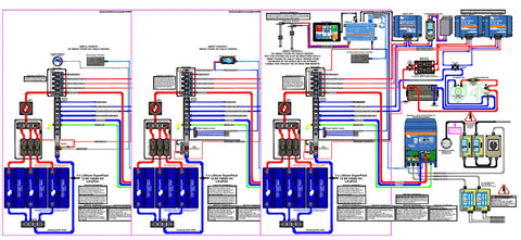
Each basic system contains a 3kVA MultiPlus and 3 Lithium "drop-in" batteries for a total of 300Ah. The BMS of the Lithium batteries will provide protection from a charge and discharge point of view.
There are multiple charge possibilities available for the batteries in this setup (combinations are also possible):
- AC Power that enables the 3kVA MultiPlus Inverter/Charger (120A) to charge.
- DC Power from Solar panels that enables the Smart Solar MPPT 100|50 to charge.
- DC engine charging power that enables both Orions Tr Smart 12|12-30 to charge (60 A).
AC Power will be available from the 3kVA MultiPlus Inverter/Charger the moment it has been switched on. This means that without any AC power on the input, the MultiPlus will give you 3kVA of inverter power on AC OUT-1. The moment AC Power is available on input AC IN-1, AC Power will be used to charge the batteries and also is available for loads connected to AC OUT-1. The second AC output AC OUT-2 is live only when AC power is available on the input of the MultiPlus. DC equipment like lights and pumps can be connected behind a DC switch panel and a small negative Busbar.
Version 1, the simple version, has a BMV-712 Smart Battery Monitor and a Digital Multi Control. With the BMV one can check that the batteries are not being depleted and to check the State Of Charge (SOC), Voltage, Amps, hours to go and so on. With the Digital Multi Control one can adjust the available AC power to the maximum AC current the MultiPlus will use. One can also switch the MultiPlus remotely On/Off or to Charger-Only. Both devices will help you control your “on board” AC and DC power availability.
Version 2, the smart Version-1, has a SmartShunt and a VE.Bus Smart Dongle. With the SmartShunt one can check that the batteries are not being depleted and to check the State Of Charge (SOC), Voltage, Amps, hours to go and so on. With the VE.Bus Smart Dongle one can keep a watchful eye over the MultiPlus and adjust the available AC power to the maximum AC current the MultiPlus will use. One can also switch the MultiPlus remotely On/Off or to Charger Only. The Dongle also measures the battery temperature, Battery Charge/discharge, Voltage and Amps, AC Input and Output Voltage, Amps, Power and Frequency. Both devices will help you to control your “on board” AC and DC power availability.
Version 3, the smart Version-2, has a SmartShunt and a Cerbo with a GX Touch 50 display and an optional Digital Multi Control. With the SmartShunt connected to the Cerbo one can check that the batteries are not being depleted and to check the State Of Charge (SOC), Voltage, Amps, hours to go and so on. The Cerbo can also be used to keep a watchful eye over the MultiPlus and for instance adjust the available AC power to the maximum AC current the MultiPlus will use. One can also switch the MultiPlus remotely On/Off or to Charger Only. The Cerbo also displays Battery Voltage and Amps, AC Input and Output Voltage, Amps, Power and Frequency and so on.
The main system
The main system includes 3 x 100Ah Lithium batteries. Following the drawing from the bottom-left, all positive battery terminals are connected to an individual ANL fuse-holder with a 150A fuse. The top side of the ANL fuse holders are connected together with use of a Victron Busbar. On the same Busbar is a fuse holder connected for a BMV-712 monitor with its Shunt or for a SmartShunt depending on what monitoring equipment is being used. A 1A-fuse will keep the power on 24-7. Between the 3 ANL fuse holders is a cable connection that runs to the Victron Main Switch and from the Main Switch a cable connection has been made to a Victron positive Busbar that connects to 5x Victron modular Mega fuse holders.
All 3 negative battery terminals are directly connected to a Victron Busbar. From this Busbar a cable connection runs to the battery connection of a Shunt. The Shunt model depends on what monitoring equipment is being used. From the user side of the Shunt a connection has to be made to the Central Negative Busbar. One can use a piece of tinned Copper Busbar for this, or a cable connection. Possibly also connected here is a small negative Busbar that could be needed for a VE.Bus Smart Dongle negative connection or for a Cerbo negative connection depending on what monitoring equipment is being used and some other small users for future use.
Version 1, the simple version with BMV
The BMV-712 used in this version has 2 positive connection terminals, one for its own power and measurements named B1 and one called B2. The B1 connection comes from the Positive Busbar for the batteries and a 1A fuse also as explained above. The B2 connection is being used to measure the Battery Voltage of the Van’s Starter battery with a In-Line fuse of 1A to be connected close to the positive starter battery terminal and connect to the B2 connection of the Shunt of the BMV-712. The negatives of the starter battery and the service batteries have to be connected together to make this work (this connection is available in all 3 versions). The SmartShunt VE.Direct connection on the BMV-712 will not be used here.
Version 2 & 3, the smart Version-1 & 2 with SmartShunt or Cerbo
The Smart Shunt 500A has 2 positive connection terminals, one for its own power and measurements named Vbatt+ and one called Aux. The Vbatt+ connection comes from the Positive Busbar for the batteries and a 1A fuse also as explained above. The Aux connection is being used to measure the Battery Voltage of the Van’s Starter battery with the extra supplied In-Line fuse of 1A to be connected close to the positive starter battery terminal and connects to the Aux connection of the SmartShunt. The negatives of the starter battery and the service batteries have to be connected together to make this work (this connection is available in all 3 versions). The Smart Shunt VE.Direct connection will not be used in Smart Version-1, but will be in Smart Version-2. A VE.Direct cable has to be connected between the Cerbo and SmartShunt and by doing this all battery information will be available on the GX Touch-50 screen.
Main fuses and busbar
The Victron positive Busbar with 5x Victron modular Mega fuse holders is easy to setup. The 5x modular Mega fuse holders can be connected by their Dovetail feature and the Positive Busbar fits over 1 side of the Mega fuse holder connections. This block of 5 Mega main fuse holders is the centre DC distribution point of the installation. It is very important NOT to install any main fuses until one has double checked all connections are correct. Always start with connecting the negative cable for each user to the Central Negative Busbar before connecting the positive to its dedicated Main Fuse position. Read the supplied manuals for additional information.
- The first fuse position holds a 100A fuse for the DC switch panel together with its Central Negative Busbar connection. The fuse size is an example only and should be adjusted to what is needed from a load size point of view.
- The second fuse position holds a 60A fuse together with its Central Negative Busbar connection for the output of a SmartSolar MPPT 100/50.
- The third fuse position holds a 60A fuse together with a combined negative for: Engine, Orion-1, Orion-2 and Central Negative Busbar.
- The fourth fuse position holds a 60A fuse together with a combined negative for: Engine, Orion-1, Orion-2 and Central Negative Busbar.
- The fifth fuse position holds a 400A fuse together with its Central Negative Busbar connection for the biggest device in this installation, a 3kVA MultiPlus inverter/charger. Keep the distance between the Main fuses/Central Negative Busbar and the MultiPlus as short as possible. If that can not be achieved, it will be difficult to only use one positive and one negative cable to power up the MultiPlus properly. Read the MultiPlus manual carefully to proceed further.
The PE/Earth connection will be dealt with later in the MultiPlus section.
Digital Multi Control (Version 1 and 3)
With the Digital Multi Control (DMC), one can remotely view and adjust the AC input current of your MultiPlus in a direct and easy way by the turn of a button, and you can switch your MultiPlus remotely ON or OFF, or to Charger Only.
VE.Bus Smart Dongle (Version 2)
The VE.Bus Smart Dongle can remotely monitor and control the 3kVA MultiPlus inverter/charger via Bluetooth and the VictronConnect app. The inverter/charger can be switched to On, Off or charger-only, the AC input current limit can be adjusted and the AC and DC parameters, device status, warnings or alarms can be monitored. The positive power for the Dongle comes from a 1A fuse connected to the Victron positive Busbar with 5x Victron modular Mega fuse holders. The negative power for the Dongle comes from the small negative Busbar.
Cerbo GX with GX Touch 50 Display (Version 3)
The Cerbo allows you to monitor your installation through the internet from anywhere in the world by using the Victron VRM portal or the Victron connect app. The Cerbo also provides firmware updates and settings changes. This information from the Cerbo can be viewed on the GX Touch 50 display or the Remote Console, VRM Dashboard, Advanced VRM Widgets, VRM App Widgets, and VE.Can/NMEA 2000. This all is clearly explained in the Cerbo manual.
The positive power for the Cerbo comes from a 1A fuse connected to the Victron positive Busbar with 5x Victron modular Mega fuse holders. The negative power for the Cerbo comes from the small negative Busbar. The GX Touch 50 Display HDMI connector with attached USB power cable is connected to the HDMI port of the Cerbo and the USB cable directly next to it. The VE.Bus cable coming from the 3kVA MultiPlus inverter/charger and the VE.Bus cable coming from optional Digital Multi Control both go into a VE.Bus port of the Cerbo. The Ethernet cable and its connector, to connect to the VRM Portal (if available), will go into the Network port of the Cerbo. The VE.Direct cable and connector from the SmartShunt go’s into a VE.Direct port of the Cerbo and the same for the VE.Direct cable and connector from the SmartSolar MPPT 100/50. Also made visible and connected to the Cerbo here is Tank measurement. Two resistive hard wired tank senders are connected to Tank Level port 1 and 2. The tank level ports can each be configured to work with either European (0 - 180 Ohm), or US tank senders (240 - 30 Ohm) standards, or one can configure a custom Ohm resistance range between 0 Ohm and 300 Ohm (requires firmware v2.80 or higher).
These are all the Cerbo connections in this installation, but there are many more connections that can be made, have a look at the Cerbo manual for more information.
SmartSolar charge controller MPPT 100/50
In the drawing, the Victron SmartSolar charge Controller MPPT 100/50 can be found next to the Cerbo. Also visible here is a PV breaker/Isolator. The Solar array portrayed is for illustration only. DC power from the solar PV array first passes through the PV breaker/Isolator and then connects to the MPPT PV input connections. The positive DC Output connection of the MPPT connects to the second fuse position of the 5x modular Mega fuse holders as explained previously. The second fuse position holds a 60A fuse together with its Central Negative Busbar connection for the MPPT output. The VE.Direct cable and connector from the MPPT has been connected to the Cerbo VE.Direct Port in Version 3.
Orion-Tr Smart 12/12-30 DC/DC converters
Two Orion Tr Smart 12/12-30 DC/DC converters can be seen in the drawing next to the PV breaker/isolator and solar array. The Orions are connected in parallel and will give a total charge current of 60A. Non-isolated models are used here, but Isolated models can also be used especially when one needs to prevent any interference with sensitive engines CAN bus systems.
Both Orion L & H connections are bridged and this means that the Orions need to be configured for auto start-stop mode and configured for either a normal or a smart alternator. Read the manual carefully and change settings accordingly. The Power input for each Orion comes from the starter battery positive through individual main fuses of 60 Amp each and from the starter motor negative connection-31 (Red & Black Dual Victron terminal stud). The positive DC Output connection of Orion Tr Smart-1 connects to the third fuse position of the 5x modular Mega fuse holders as explained previously and the positive DC Output connection of Orion Tr Smart-2 connects to the fourth fuse position. The third and fourth fuse position both hold a 60A fuse together with its combined Central Negative Busbar connection. The Central Negative Busbar is connected with the negative outputs of Orion Tr Smart 1 & 2, the engine negative and the Starter Battery negative by means of a Black Dual Victron terminal stud.
Engine System
The starter circuit of the engine with Starter Battery and Chassis ground connections and alternator with main fuse and Starter Motor visible in this drawing is an example of how to connect your Victron products.
MultiPlus Inverter/Charger 3kVA/12V 230V/50Hz AC
Below the starter circuit in the drawing, the MultiPlus can be seen. The MultiPlus should be mounted in a dry, well-ventilated space and where the MultiPlus can cool itself properly. Leave at least 10cm or 4” of space around the device.
Most connections to and from the Multiplus have been discussed above; in summary: The DC power to and from the MultiPlus connects to the fifth fuse position holding a 400A fuse, together with its Central Negative Busbar connection. Incoming AC power into the Van or Motorhome comes through a Shore Power connection of normally 16A. From there it passes through an incoming AC breaker box towards a possible change over switch for: Shore power-0-Generator power. If there is a generator installed with a breaker box, the breaker for Shore power and the breaker for Generator power will connect to its individual change over switch connections before connecting to the MultiPlus AC IN-1 connections. If no change-over switch and generator are in use here, the breaker for shore power connects directly to the MultiPlus AC IN-1 connections.
AC OUT-1 of the MultiPlus is connected to an AC breaker box with a MCB/RCD device and some breakers. The amount of breakers depends on the setup of the Van or Motorhome. These are NO Break AC outputs and as the name suggests, are constantly powered through the MultiPlus Inverter.
AC OUT-2 of the MultiPlus is also connected to an AC breaker box with a MCB/RCD device and some breakers. The amount of breakers also depends on the setup of the Van or Motorhome. These are switched AC outputs and as the name here suggest are switched off when there is no incoming AC power available. AC OUT-2 is live only when AC power is available on the input of the MultiPlus with a 2 minute connect delay.
When any other AC power connections are made between the shore power connection and the MultiPlus or between the Generator power and the MultiPlus, extra MCB/RCD devices with breakers need to be installed for your own safety.
The MultiPlus has two VE.Bus connections; In version 1, one is used for the Digital Multi Control and the other one is Spare. In version 2, one is used for the VE.Bus Smart Dongle and the other one is Spare. In version 3, one is used for the Cerbo and the other one is Spare.
The MultiPlus has a Case Ground connection-L that should be connected to the Central negative Busbar as shown in this drawing. The Case Ground cable should be one size smaller compared to its total connected negative.
All shown connections in the drawing are made according to CE/ABYC regulations. This is a NON-Isolated DC System setup. Read the MultiPlus manual carefully to proceed further.
Software settings
- When setting up a new system, It will be good practice to update all Victron devices to the latest available Software/Firmware.
- The Victron Smart Shunt 500A can be set, monitored and updated with use of the VictronConnect App. Don't forget to set the Battery capacity.
- The Victron Battery Monitor BMV-712 Smart can be set and monitored through its own device settings or it can be set, monitored and updated with use of the VictronConnect App. Don't forget to set the Battery capacity.
- The Victron VE.Bus Smart Dongle can be set, monitored and updated with use of the VictronConnect App.
- The Victron Digital Multi Control panel comes ready out of the box and does not need any updates.
- The Victron SmartSolar MPPT 100/50 can be set, monitored and updated with use of the VictronConnect App. It must be programmed for Li-Ion mode and 12V.
- The Victron Orion Tr Smart 12/12-30A DC/DC Chargers can be set, monitored and updated with use of the VictronConnect App and must be programmed for Li-Ion mode. Adjust settings for start and stop charging according to installed alternator and if it is a normal or smart alternator.
- The Victron Cerbo GX Device can be updated to the latest Firmware in two different ways:
- Update via the internet, either manually or let it check for new updates every day.
- Update it from a microSD-card or USB-stick, consult the Cerbo manual.
- The Victron MultiPlus can be set, monitored and updated with use of the MK3-USB interface and VEConfigure software (Windows only) or use the VictronConnect App (Multi Platform). Limitations of VictronConnect are that one can not add assistants, use Virtual Switch and/or change the Grid Code.
Wiring Calculations
It is not possible to give specific wire sizes, as each setup is different. There is a very handy tool available from Victron called Victron Toolkit for Android and iPhone users. In this app you will find Cable Calc that will help you size any cable for AC and DC. This will help you find all the right cable sizes for your project.
Wiring Unlimited
This is a book freely available from the Victron Website and contains information about electrical wiring for systems containing batteries, inverters, charger, inverter/ chargers and so on. With this book Victron aims to explain wiring basics of electrical systems. This book helps to explain the importance of ‘getting it right’ and the issues that might happen when a system has inferior wiring. It also assists electrical installers or users to troubleshoot issues that have arisen from bad wiring.
Victron-Remote-Monitoring / VRM app or website
Monitoring of your installation can be done either with the Cerbo or from anywhere in the world using an internet connection as shown in the drawing with VRM World that connects to the Victron VRM portal either using the Victron connect app or website. Just login to your VRM account or setup a new one and tap on your account to view your installation. You can for instance set alarm status information for the state of charge or SOC and this will automatically warn you when a certain level has been reached. This is extremely useful for long time parking or winterizing mode and.…. It is free of charge ! For more info read the latest available VRM manual. The VRM app is available for Android and iPhone users.
Not using your vehicle for a longer period of time
Make sure to switch the MultiPlus to charger only. This prevents the inverter from draining the batteries when no AC input power is available. When parked outside, the solar panels will maintain the batteries, but only when parked un-shaded.
Winterizing
Before putting the Van or motorhome in hibernation for winterising, make sure to fully charge the batteries first. Then switch off the MultiPlus and the main switch. The Smart Shunt is on, 24-7. Check on a regular interval if the batteries are not losing too much capacity and make sure to prevent freezing at all times. A regular interval is 4-6 weeks. Installing a small Victron maintenance charger for wintertime is a very good investment. With for instance a Victron Blue Smart IP65 Charger 230V/12V/10A, you can switch off the MultiPlus and only use the maintenance charger and monitor your system with use of the VRM app or website. You do need an Internet connection to make this work and Victron also has a solution for this with the GX LTE 4G cellular modem.
List of materials needed:
- Battery Monitor BMV-712 Smart (1)
- Battery switch on/off 275A (1)
- ANL Pre-Main fuse holders for the batteries (3)
- Blue Sea ANL 150A Main fuse (3)
- Blue Sea Mini Busbar - 5 Gang with Cover (1)
- Breaker box PV with DC breaker isolator for solar Array (1)
- Breaker box MultiPlus AC OUT-1 & AC OUT-2 (1)
- Breaker box MultiPlus AC Shore power Input and AC Generator power Input (1)
- Busbar 600A 4P + cover (2)
- Busbar 600A 8P + cover (1)
- Busbar to connect 5 Modular fuse holders for Mega-fuse (1)
- Change Over Switch between AC Shore and ACmGenerator power with Off position, routing AC power to MultiPlus AC IN-1 (if needed) (1)
- Cerbo GX (1)
- Digital Multi Control 200/200A GX (1)
- Dual Terminal Stud M8-linked set (1 red/1 black) Set of 2
- Fuse holder 2AG or 5x20mm by Little Fuse including fuses if needed 150 series (7)
- Fuse holder for MEGA-fuse (Orion Tr inputs) (2)
- GX Touch 50 Display (1)
- Batteries 12,8V/100Ah (3)
- MEGA-fuse 60A/32V (package of 5 pcs) (1)
- MEGA-fuse 100A/32V (package of 5 pcs) (1)
- MEGA-fuse 400A/32V (package of 5 pcs) (1)
- Modular fuse holder for Mega-fuse (1 till 5) (5)
- MultiPlus 12/3000/120-16 230V (1)
- Orion-Tr Smart 12/12-30A non Isolated DC-DC charger (2)
- Power Inlet 16A stainless steel with cover (1)
- Power Cord 15m 16A for shore power inlet (1)
- SmartShunt 500A/50mV (1)
- SmartSolar MPPT 100/50 (1)
- VE.Bus cables: from Multiplus to: Cerbo or VE.Bus Smart Dongle or Digital Multi Control and from Cerbo to DMC
- VE.Bus Smart dongle (1)
- VE.Direct cables: from MPPT to Cerbo, from Smart Shunt to Cerbo.
Click here to find a special collection of the above-mentioned products.
In order to find any additional information, please have a look at https://community.victronenergy.com/index.html
Click here for a printable version from the Victron website.
Source: Victronenergy.com
Installations must be done by a qualified electrician/technician and must adhere to local wiring regulations and standards. Amperion - SunStore will not be held liable for any product malfunctions as a result of incorrectly installed systems.